🔄 555 Timer Applications: Astable Mode
In the last lesson, we learned about monostable mode (one-shot).
Now we explore astable mode: the 555 timer as a free-running oscillator.
No trigger needed. It oscillates continuously, producing a square wave output.
🎯 What is Astable Mode?
Astable = not stable in any state
The output:
- Goes HIGH for a time
- Goes LOW for a time
- Repeats forever
Perfect for:
- LED flashers
- Tone generators
- Clock signals
- PWM generation
- Alarm circuits
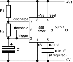
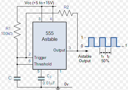
🏗️ The Astable Circuit
- Vcc to pin 8
- Pin 4 and 8 tied together (RESET high)
- R1 from Vcc to pin 7 (DISCHARGE)
- R2 from pin 7 to pin 6/2 (THRESHOLD/TRIGGER tied together)
- Capacitor C from pin 6/2 to ground
- Pin 5 bypassed with 0.01µF to ground
- Pin 3 (OUT) to load
- Pin 1 to ground
Key Differences from Monostable
- Pins 2 and 6 connected together (self-triggering)
- Two resistors (R1 and R2) instead of one
- No external trigger needed
- Continuous oscillation
📊 How It Works
Charging Phase (Output HIGH)
- Capacitor charges through toward Vcc
- When voltage reaches → upper comparator triggers
- Output goes LOW
- Discharge transistor (pin 7) turns ON
Discharging Phase (Output LOW)
- Capacitor discharges through to ground (via pin 7)
- When voltage falls to → lower comparator triggers
- Output goes HIGH
- Discharge transistor turns OFF
- Cycle repeats!
📐 The Timing Formulas
HIGH Time
Capacitor charges through both resistors.
LOW Time
Capacitor discharges through only .
Total Period
Frequency
Duty Cycle
Since always includes and only includes :
The duty cycle is always > 50% in standard astable configuration!
For 50% duty cycle: must be very small (or use modified circuit).
🔆 Design Example 1: LED Flasher (1 Hz)
Goal: Flash LED at 1 Hz (on for 0.5s, off for 0.5s)
Requirements:
- Duty cycle ≈ 50%
Design:
For 50% duty cycle: Make small, large
Let's try: ,
For :
Use
Verify:
- Total period = 0.949s
- Frequency = 1.05 Hz ✓
- Duty cycle = 51% ✓
Close enough!
🎵 Design Example 2: Audio Tone Generator (1 kHz)
Goal: Generate 1 kHz square wave for simple beeper
Design:
Choose (good for audio frequencies)
Let's choose:
Use standard values: ,
Result: 1 kHz tone that can drive a small speaker (through capacitor)!
🎚️ Variable Frequency Oscillator
Replace with a potentiometer for adjustable frequency!

- R1 = 1kΩ (fixed)
- R2 = 10kΩ potentiometer (variable)
- C = 100nF
- Output frequency adjustable from ~700 Hz to 7 kHz
Applications:
- Simple theremin
- Siren effects
- Function generator
- Metal detector
🎛️ True 50% Duty Cycle Circuit
Standard astable has duty cycle > 50%. For exactly 50%, use this trick:
- Add diode D1 in parallel with R2, cathode toward pin 7
- Add diode D2 in series with R2, anode toward capacitor
- Now capacitor charges through R1 + D1
- Discharges through R2 + D2
Result:
Choose → Perfect 50% duty cycle!
⚡ PWM (Pulse Width Modulation) Generation
By varying duty cycle, you control average power delivered to load.
Simple PWM Circuit
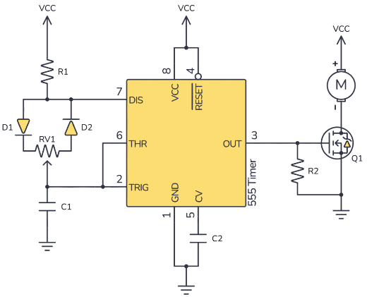
- Use potentiometer for R2
- As R2 increases → duty cycle increases → brighter LED/faster motor
Applications:
- LED dimming
- Motor speed control
- Heater power control
- Servo position control (needs precise timing)
🔊 Audio and Sound Projects
1. Siren Generator
Two 555 timers:
- 555 #1 (astable): Slow oscillator (1-2 Hz)
- 555 #2 (astable): Audio oscillator (500-1500 Hz)
- Connect output of #1 to control pin (5) of #2
Result: Pitch varies up and down like a siren!
2. Musical Doorbell
555 astable + speaker + power-on reset circuit
- Powers on → plays tone
- Frequency determines musical note
Frequencies for notes:
- Middle C: 261.6 Hz
- D: 293.7 Hz
- E: 329.6 Hz
- F: 349.2 Hz
- G: 392.0 Hz
- A: 440.0 Hz
- B: 493.9 Hz
Calculate R and C for desired note!
3. Metronome
Adjustable frequency (40-200 BPM)
- Audio click
- Visual LED flash
- Adjust tempo with potentiometer
💡 LED Effects
Flashing LED (Knight Rider Scanner)
Use 555 astable to clock a decade counter (like CD4017).
- Each clock pulse advances to next output
- Connect LEDs to outputs
- Creates scanning/chasing effect
RGB Color Mixer
Three 555 timers with different frequencies:
- Red LED: 3 Hz
- Green LED: 5 Hz
- Blue LED: 7 Hz
- Combine → complex color patterns!
🏭 Industrial Applications
1. Watchdog Timer
Monitor that a system is alive:
- 555 astable generates periodic pulses
- System must reset/retrigger timer
- If system hangs → timer keeps running → alarm
2. Speed Controller
PWM from 555 controls motor speed:
- Low duty cycle → slow speed
- High duty cycle → high speed
- Smooth speed control
3. Flashing Warning Light
Safety equipment, emergency vehicles:
- High visibility
- Low power consumption
- Reliable (555 never fails!)
🔬 Advanced: Voltage-Controlled Oscillator (VCO)
Control 555 frequency with external voltage!
Method: Apply control voltage to pin 5 (CTRL)
Normally pin 5 is at . By changing this:
- Higher voltage → higher thresholds → longer timing → lower frequency
- Lower voltage → lower thresholds → shorter timing → higher frequency
Applications:
- Frequency modulation (FM)
- Analog synthesizers
- PLL (Phase-Locked Loop) circuits
- Sensor-controlled oscillators
🎯 Frequency Ranges and Component Selection
| Frequency Range | R1 + 2R2 | Capacitor | Applications |
|---|---|---|---|
| 1 Hz - 10 Hz | 100kΩ - 1MΩ | 10µF - 100µF | LED flashers, slow timers |
| 10 Hz - 100 Hz | 10kΩ - 100kΩ | 1µF - 10µF | Low-frequency signals |
| 100 Hz - 10 kHz | 1kΩ - 10kΩ | 10nF - 1µF | Audio, tones, alarms |
| 10 kHz - 100 kHz | 1kΩ - 10kΩ | 100pF - 10nF | Clock signals, PWM |
| 100 kHz - 500 kHz | 1kΩ | 10pF - 100pF | High-speed switching |
- Minimum: Limited by capacitor leakage (~0.01 Hz practical limit)
- Maximum: ~500 kHz (bipolar 555), ~2 MHz (CMOS 555, like TLC555)
Above 500 kHz: Consider using crystals, dedicated oscillators, or microcontrollers.
🛠️ Troubleshooting Astable Circuits
| Problem | Likely Cause | Solution |
|---|---|---|
| No oscillation | Wrong connections, bad power | Check all pins, verify Vcc |
| Wrong frequency | Wrong R or C values | Recalculate, measure components |
| Unstable frequency | Bad capacitor, noise | Use quality cap, add bypass caps |
| Distorted waveform | Excessive load on output | Add buffer, reduce load |
| Frequency drifts | Temperature, bad components | Use stable components (C0G caps) |
| Won't start | Pin 4 (RESET) floating | Tie pin 4 to Vcc |
🧪 Lab Exercise 1: Build a Simple Alarm
Objective: Create a loud alarm that can be turned on/off
Circuit:
- 555 astable @ 2 kHz (annoying frequency!)
- Output drives piezo buzzer through 100µF capacitor
- Switch to enable/disable
- Add second 555 (monostable) for auto-shutoff after 30 seconds
Components:
- NE555 × 2
- Resistors, capacitors (calculate values!)
- Piezo buzzer
- Toggle switch
- 9V battery
Bonus: Add potentiometer to adjust tone pitch
🧪 Lab Exercise 2: Adjustable LED Dimmer
Objective: Control LED brightness with PWM
Circuit:
- 555 astable with variable duty cycle
- Frequency: ~500 Hz (above flicker threshold)
- 10kΩ potentiometer for duty cycle control
- High-brightness LED as load
Components:
- NE555
- 1kΩ, 10kΩ pot, capacitors
- 2 diodes (1N4148) for 50% circuit
- High-brightness LED + resistor
Learning: Observe how duty cycle affects brightness
- Use oscilloscope to view PWM waveform
- Measure average voltage at LED with multimeter
🎲 Fun Project: Electronic Dice
Complete circuit using what we've learned:
- 555 astable (this lesson): Fast oscillator (~1 kHz)
- Binary counter: Counts 555 pulses (0-7)
- Button: Stops/starts counter
- Decoder: Converts binary to 7-segment display
- Display: Shows "dice" number (1-6)
Your task: Build the 555 astable section!
- High frequency (so counting appears random)
- Reliable oscillation
- Low power
✅ Astable Mode Summary
Key Formulas:
Key Points:
- Continuous oscillation (no trigger needed)
- Capacitor charges through
- Capacitor discharges through only
- Duty cycle > 50% (unless modified with diodes)
- Variable frequency with potentiometer
- Adjustable duty cycle = PWM capability
Common Applications:
- LED flashers
- Tone generators
- Clock signals
- PWM controllers
- Sirens and alarms
- VCOs (voltage-controlled oscillators)
🎓 Astable vs. Monostable Comparison
| Feature | Monostable | Astable |
|---|---|---|
| Triggering | External trigger needed | Self-triggering |
| Output | Single pulse | Continuous square wave |
| Pins 2 & 6 | Separate | Connected together |
| Resistors | One (R) | Two (R1, R2) |
| Use case | Delays, timeouts | Oscillators, clocks |
🎓 Looking Ahead
The 555 timer is amazing, but it has limitations:
- Frequency stability (affected by temperature, supply voltage)
- Precision (component tolerances)
- Complexity (for more advanced timing needs)
For more precise timing, you'll want:
- Crystal oscillators (next level up)
- Microcontrollers (ultimate flexibility)
- Function generators (lab instruments)
But for simple, reliable, cheap oscillators? 555 is unbeatable!
📚 Further Exploration
- Build astable circuits at different frequencies
- Measure actual vs. calculated frequency
- Observe waveforms with oscilloscope
- Try PWM dimming with different loads (LEDs, motors)
- Combine multiple 555 timers for complex effects
- Research CMOS 555 (TLC555, ICM7555) for lower power